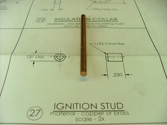
All right, so where were we? Ah yes the ignition stud. This part is made from a 3/16 copper rod that is supplied in the materials kit. Note: Copper is a very stubborn material to cut and thread. It is like cutting hard bubble gum and loves to clog bits and wad-up on cutting tools. Precise finishes are a challenge and require a bit of trail-and-error for success.
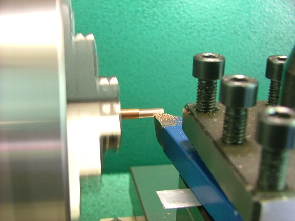
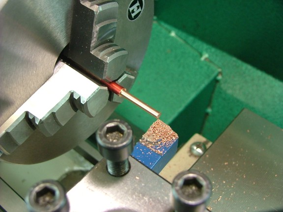
I started off the part by turning down the rod to a diameter of .157. I used a carbide tool bit that was precisely sharpened on a silicon carbide grinding wheel. You will notice that I used my shimming/rocker method to align the tool bits height for a proper cut. Note: I cut the rod in very shallow passes which did not allow the copper to ball-up on the tool bit.
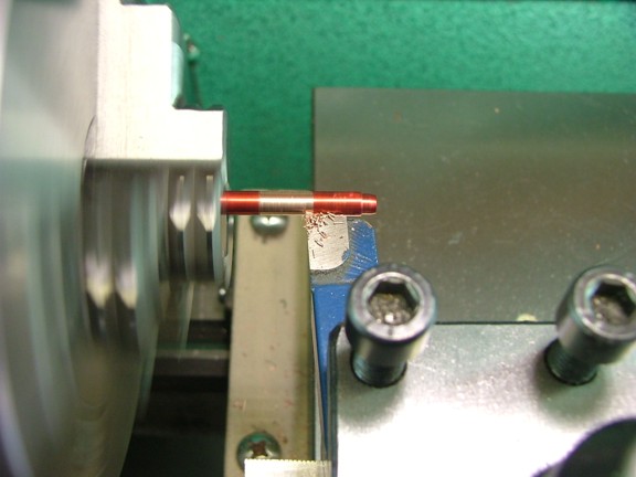
I now cut a small lead-in chamfer for the contact stud. This will help the stud to press into the timing gear later on.
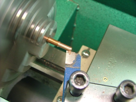
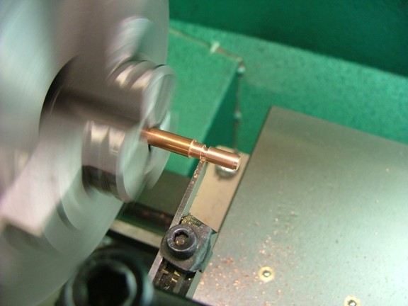
Lastly a HSS parting tool was used to neck down the rod at about .300 from the end. I left a .100 diameter neck to allow me to drive in the stud and break off the rod when set into the gear.
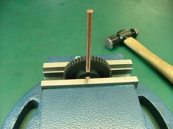
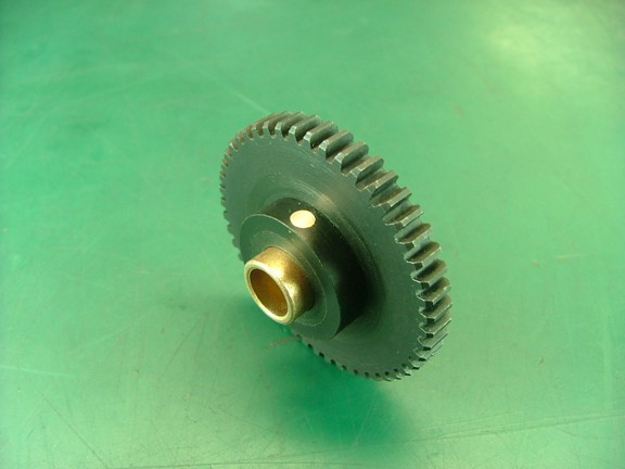
I mounted up the timing gear in a vise and carefully drove the contact stud into the gear. I was careful not to go too far into the bore which would obstruct the gear bushing later on.
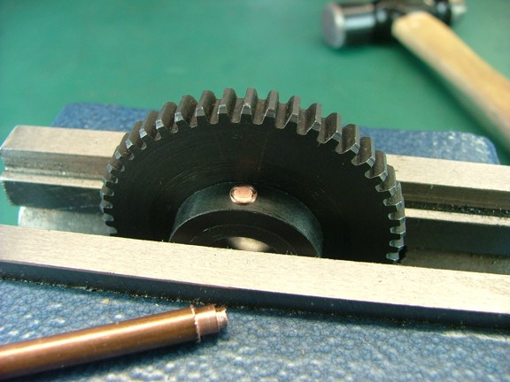
I could now break off the remaining rod...
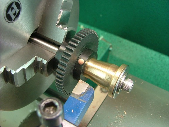
I moved the gear back to the lathe and carefully trimmed the stud flush with the collar as seen below...
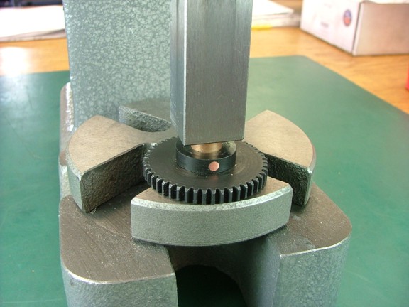
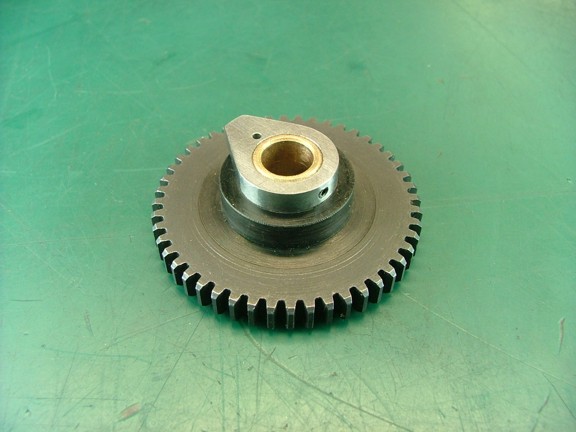
I now moved the gear over to the arbor press and drove the timing gear bushing into the hub until it was flush with the front of the gear.
A quick fit check...
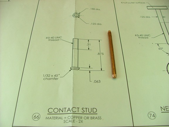
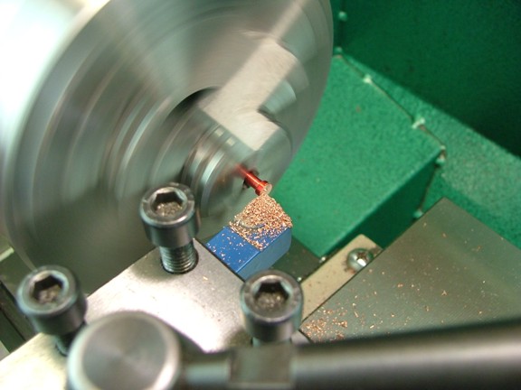
It was now time to make the contact stud for the timing lever. This is made from the same piece of copper as before.
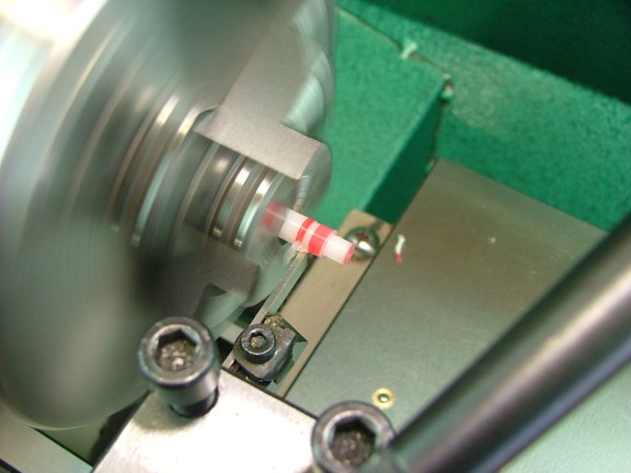
I started out by marking the rod with a line at .810 from the end. I then turned down the rod to a diameter of .125 up to this line.
Once again I was careful to make light passes on the rod...
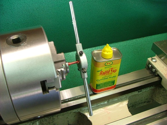
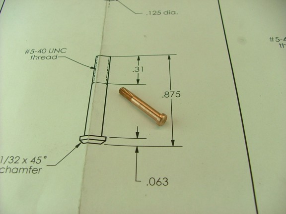
The next step is to thread the end of the stud with a 5-40 die. I marked the rod at .310 from the end to know where to stop the die and then spun the chuck by hand while holding the die handle. I used a few drops of Rapid Tap which is my favorite cutting oil. This will help reduce the copper from balling up in the teeth of the die. Note: Some folks like to use whole milk as a cutting fluid for copper. I personally prefer the Rapid Tap as it does not spoil :0P
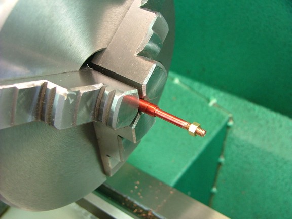
I tested out the threads with a 5-40 nut that is supplied with the screw assortment kit.
I now cut off the rod and reversed the stud in the chuck to face off the head to a thickness of .065. I then cut a bevel on the edge to allow the contact to easily ride over the timing gear (not shown).
Another small part off the list ;0)
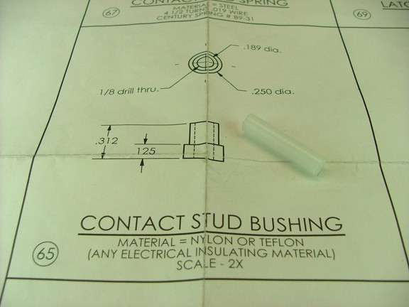
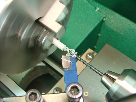
The next part to tackle is the contact bushing. This is made from a piece of 1/4 diameter Delrin rod that is supplied in the materials kit.
The first step is to bore a #30 hole 1/2 into the end of the rod...
I marked the rod at .187 from the end and then turned down the rod to .189 as the prints suggest. I then parted off the bushing at a length of .312 with the HSS parting tool.
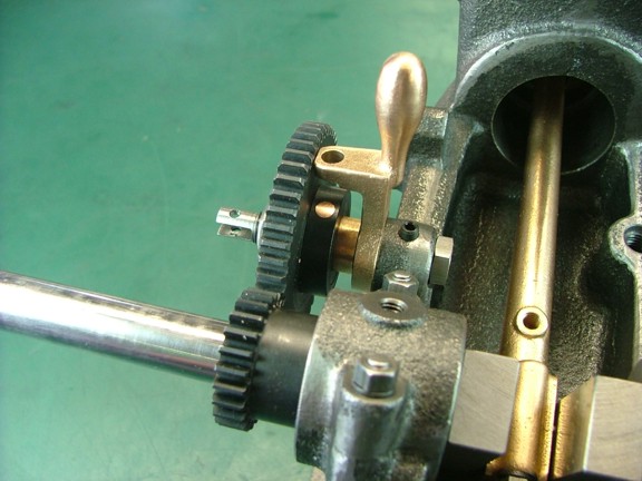
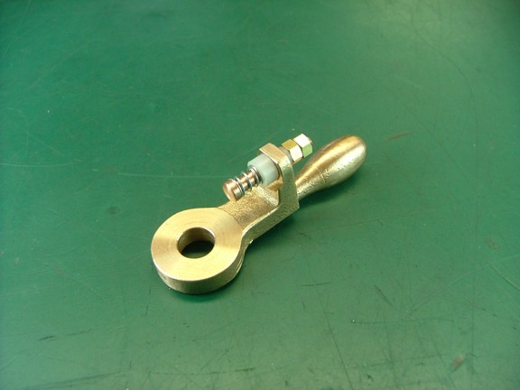
I assembled the contact stud along with the supplied contact spring and two 5-40 nuts to finish the timing lever assembly.
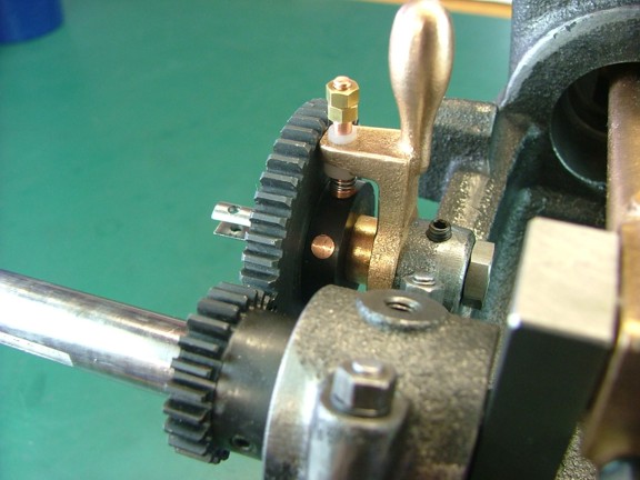
I tested the contact stud on the timing gear which worked beautifully :0)
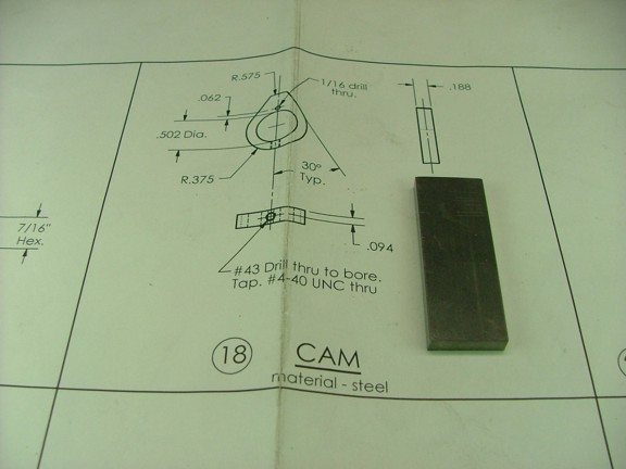
The next part to machine is the cam. This part is to be made from a piece of 3/16 x 3/4 cold rolled steel that is supplied in the materials kit. Note: This part could also be made from tool steel and then hardened once machined. My personal opinion is that this cam will not endure much mechanical abuse at 300 RPM so plain steel is perfectly fine to use for this part...
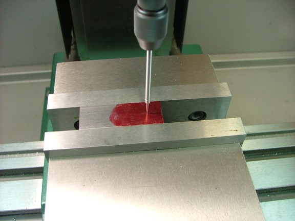
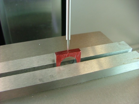
I started out by laying out a center mark (.375) on one end of the bar...
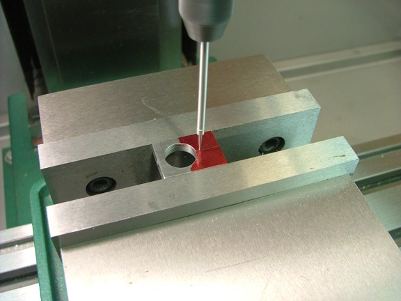
I now lined up the spindle on the mark using the wiggler tool.
I used a #2 center drill to spot the hole as usual...
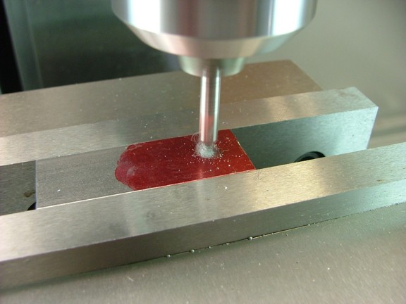
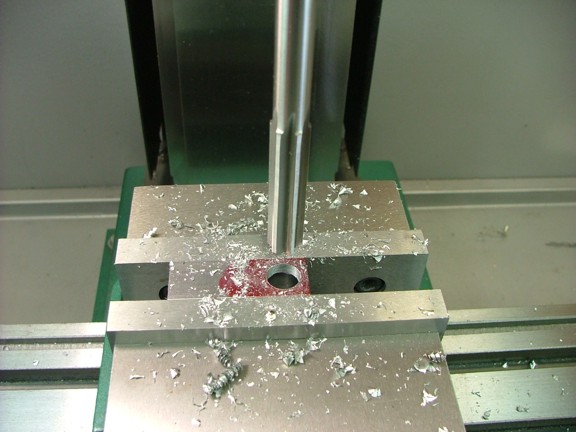
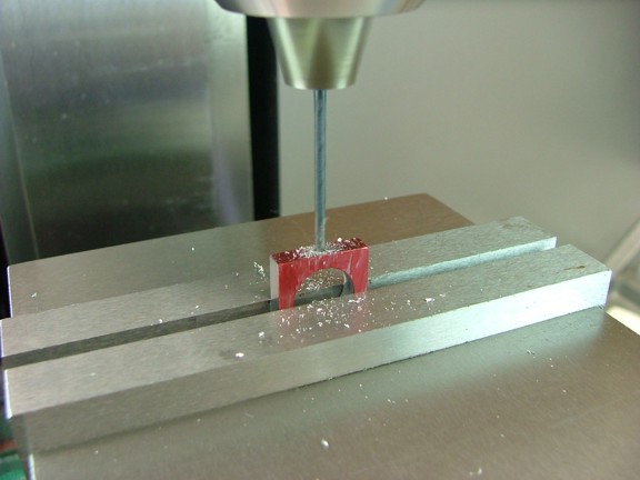
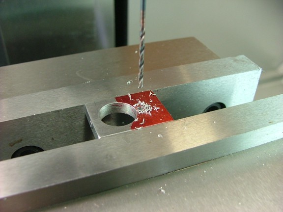
I now drilled a 15/32 hole followed by a 1/2 chucking reamer...
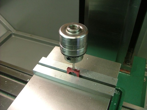
I remounted the cam in the milling vise and laid out the set screw hole as seen below.
I now drilled the hole with a #43 drill bit...
I then tapped the hole with a 4-40 tap as seen below.
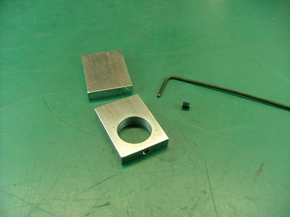
I used my bandsaw to cut the cam piece down to a length of 1 and then tested the supplied 4-40 set screw in its hole.
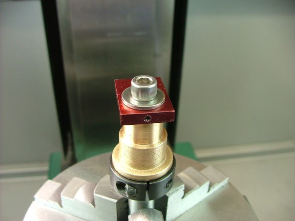
I remounted the cam in the milling vise and laid out the roll pin hole which will be needed to fix the cam to the timing gear later on.
The hole was drilled with a 1/16 bit as seen below.
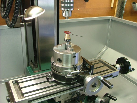
The next step is to cut the cams profile. I set up the cam on my turning arbor which is mounted on the rotary table.
I used the 4-40 set screw to lock the cam into place on the arbor. You wouldnt want the cam to shift during this process.
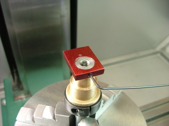
I now clamped down the cam with the turning arbors end screw to help secure the cam.
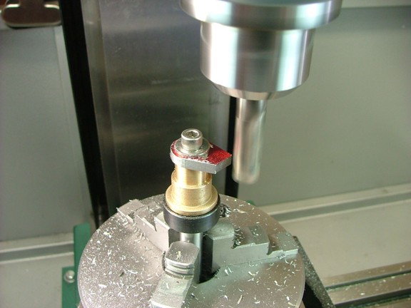
I aligned the cam so that the sides were perpendicular to the milling table while the rotary table was zeroed out. I then placed a 1/2 end mill in the spindle and started trimming the round end of the cam by turning the rotary table clockwise (against the direction of the cutting surfaces). Note: The spindle is on the same Y axis as the cam while the end mill is moved toward the arbor for progressive cuts...
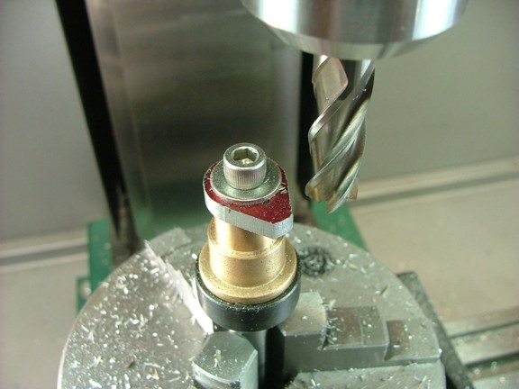
I continued cutting the round end until I could see no more layout fluid on the set screw end of the cam. I then zeroed out the X axis of the table for a reference to where the inner radius of the cam is (.375). I then positioned the cam at 30° to start cutting the lobe of the cam as seen below. Once again I continued to push the part in the opposing direction of the cutter to ensure against the tool climbing the part.
Once the two 30° sides were cut I was able to move the table over .200 (from zero) to cut the top of the lobe...
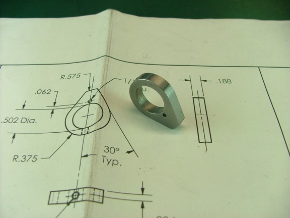
I removed the cam from the arbor and used some 320 grit sand paper on my granite surface plate to smooth off the edges of the lobe (not shown). I slightly rounded the edges of the top of the lobe however I did not round over the top. Note: some folks may be tempted to excessively round off the nose of the lobe to promote better tracking of the cam follower. I personally feel that the duration of the exhaust cycle has been engineered with this type of square cut profile and engine performance may be degraded by messing with this profile. I will be using a ball bearing for my cam follower which will ride effortlessly on this profile especially since the engine will be turning at such a low RPM. There will be no chance of floating a valve at 300 RPM ;0)
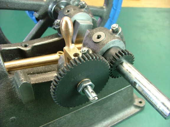
The last step is to fit check the cam on the timing gear bushing. Note: I will not drill the cams roll pin hole in the timing gear until I can set the valve timing on the engine itself...
This project is really coming along although it is producing the most ambitious build article I have written to date :0P Hopefully I am not boring my readers with a bunch of repetitive steps. I just want to be as thorough as I can with the steps taken to build this engine. Please send me some feedback to how I am doing if you like ;0) Join me again for the next episode of the Red Wing Engine Project and until then, stay creative my friends!!!