 |
|
|
|
|
|
|
|
|
 |
|
|
 |
|
 |
|
 |
|
|
|
Posted on June 10, 2011
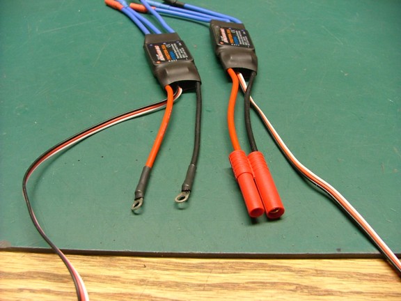
Hello folks, I am getting ready to install the Electronic Speed Controls (ESCs) that will power up the six brushless motors. For these I will be using a set of Exceed RC Volcano/Proton 30 amp ESCs (Cat #07E04) that I got from Hobby Partz on sale for about $14 each (You can also look up Hobbywing Pentium-30A which I believe is the same ESC or Volcano-30 (07E04)).
I am told that these ESCs are a great value and from what I see so far I cant disagree. I am using 30 amp ESCs in leu of 25 amp units so that I have a larger margin for upgrading my motors to a bigger size should I decide to do so later on. The larger ESCs also stay cooler than smaller ones granted they are both under the same load.
To use these ESCs I will need to solder on some 14 gauge ring connectors so they can be connected to the power bus terminals of the copter. I removed the stock bullet connectors on the speed controls and soldered on the ring connectors followed by some shrink wrap tubing (seen below left)....
Note: The Exceed RC Proton 30A ESC does not support a 400Hz refresh rate and will stall under load if subjected to this rate. Flight control units with ESC outputs at 400Hz and higher should not be used with these ESCs. This includes the DJI Naza-M flight controller...
|
|
|
 |
|
|
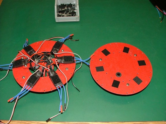
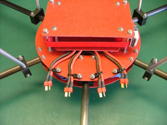
The next step was to attach all of the ESCs to the power bus terminals as seen below. I used some nylon insert locknuts to hold all of the ring connectors in place......
|
|
|
 |
|
|
To secure the ESCs I used some industrial strength adhesive Velcro tape. I applied the tape to the ESCs and also to the underside of the upper hub disk as seen below. You may notice that I also installed a 7/16 ID x 3/4 OD rubber grommet (McMaster-Carr Cat# 9600K19) for the ESC servo leads to pass through the upper disk (below right).......
|
|
|
 |
|
|
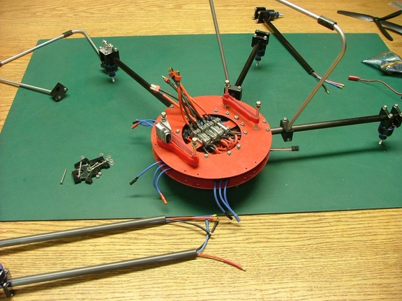
And now for the copters reassembly. I started to piece the hex together taking care not to pinch any wires in the assembly. I checked out the rotation of the motors as I plugged them in with an RC receiver and Li-Po battery (not shown). The very forward motor (#1) was set to turn clockwise (looking at the prop adaptor from the top). I then set the #2 motor (moving clockwise around the copter) to spin counterclockwise. I then moved on to #3 motor for a clockwise rotation and so on.
The counter rotation of the propellers will cancel out any yaw created by the motors of the copter making controlled flight possible. Note: Directions for setting up the rotation of the motors is described in Ken Duffeks hexacopter flight control board instruction sheet.........
|
|
|
 |
|
|
The reassembly process was finished and the copter looked like a hex once more :0)
|
|
|
 |
|
|
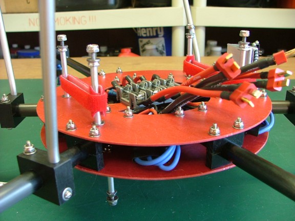
The next step was to tame the battery pigtail connectors so they cannot come into contact with each other accidentally. This is to prevent a short circuit situation as they are all connected in parallel......
|
|
|
 |
|
|
I tethered down the four battery pigtail connectors with some clamp tie cable ties which have a hole in the end which can be secured with a screw (McMaster-Carr Cat# 7295K12). Now the connectors will not contact each other when plugging the batteries in!!!
|
|
|
 |
|
|
And now to reinstall the battery tray..............
|
|
|
 |
|
|
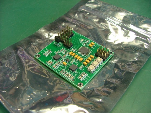
The next logical step in my project is to install the flight control board. Although I have never worked with a hexacopter or multi-copter of any kind before I am pretty sure that they dont fly real well without an on-board flight control system. That is because humans dont have the reaction/response time needed to make multiple corrections in flight attitude to keep one of these aircraft in the air (for very long anyway). To make a hexacopter fly you need an on-board flight computer to sense how the craft is moving and what corrections in attitude need be applied to keep the copter upright (along with the pilots control input of course).
The flight control board below uses a set of MEMS (Micro-Electro- Mechanical Systems) type gyroscope sensors that can detect angular acceleration. The MEMS type gyroscope uses a tiny vibrating structure much like a tuning fork to create a Coriolis Effect in the plane of vibration. Any change in movement outside of this plane can be detected by a tiny deflection of this vibrating structure (Coriolis Force). This deflection is sensed by a set of transducers and then interpreted by an internal integrated circuit that tuns the movement into an analog or digital output.
In this case the Gyros output is routed to a programmable microcontroller chip that has been loaded with a special algorithmic program that interprets the MEMS sensors data as well as the pilots input controls. This data is computed and converted to a pulse-width modulated signal that the ESCs can use to control the motors. Simple right??? :oP
|
|
|
 |
|
|
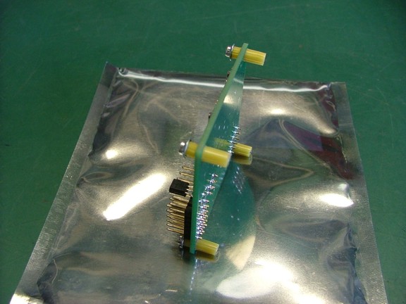
Because the MEMS type sensors used on this board use vibrating structure technology to sense movement they generally require a low vibration surface to mount to. Any high frequency vibrations can throw off the sensors and disable the control board. This is why I must devise a vibration absorbing system for the board which will isolate the sensors from any disruptive vibration caused by the brushless motors.
For this I am going to use a set of silicone tubing pieces to make a set of shock absorbers that will hopefully null out any vibration from the motors of the copter. I am going to use some plastic tubing studs to attach the board to the tubing pieces as seen below. These studs will be made out of Sullivan 2-56 nylon Gold-N-Rod pushrod tubing which I parted out of a control rod set (Cat# S503) for RC aircraft (Tower Hobbies Cat# LXFU90). I have used this stuff extensively for all kinds of things like antenna supports for 2.4 RX receivers and 2-56 rod couplings.
I cut out four 1/8 long pieces as well as four 1/4 long pieces of the Gold-N-Rod to make my attachment studs for the control board.....
|
|
|
 |
|
|
I attached the pushrod tubing to the control board using some #2 servo screws as seen below. Note: I sandwiched the board with two pieces of tubing as to avoid any metal contact with the board itself.....
|
|
|
 |
|
|
I installed a second set of 1/4 studs on the hexacopters hub disk that match the pattern of studs on the control board. Luckily I was able to drill and install these studs without taking the copter apart :0P
|
|
|
 |
|
|
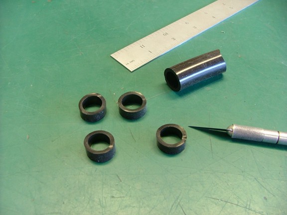
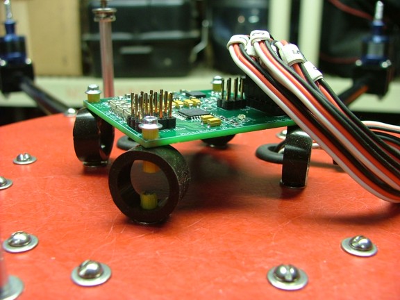
The main component to my shock absorber system is some super soft 1/2 ID x 3/32 wall silicone tubing (McMaster-Carr Cat# 5236K462). This high temp silicone is super soft with a durometer rating of 50A and can be stretched up to twice its length. My hopes are that the softness of the silicone will act like a harmonic dampener and cancel out any unwanted vibration to the flight control board.
I cut out four 5/16 wide pieces of the tubing for my vibration mounts as seen below......
|
|
|
 |
|
|
I made 1/8 holes in either side of the tubing pieces using a leather punch so that they could be mounted on the support studs I installed earlier.......
|
|
|
 |
|
|
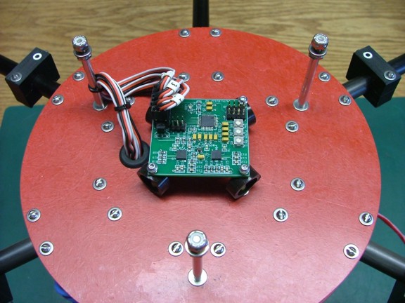
The tubing pieces were installed on the flight control board and then fitted to the copter as seen below. I then attached the ESC wires to the board leaving a loop in the wires so the board can be isolated from the main hub......
|
|
|
 |
|
|
The new shock absorbers really look like they are going to do the job however I wont know until I test them out. It may be necessary to widen the tubing pieces should the board be too loose and not sense the copters attitude correctly.....
|
|
|
 |
|
|
You may have noticed that I numbered the ESC leads with some wire numbers. I had done this when I tested out the rotation of the motors earlier.....
|
|
|
 |
|
|
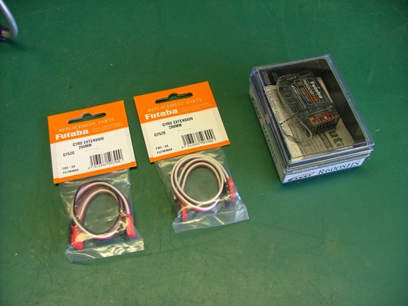
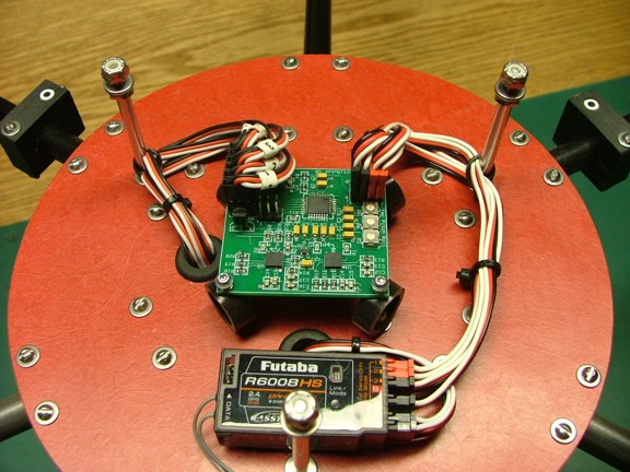
The next step in installing the electronics is adding the remote control receiver. I will be using a Futaba R6008HS 2.4 GHz FASST receiver in tandem with my 14MZ radio system of which I have had rock solid stability. In order for me to attach the receiver to the flight control board I will need some male double ended servo leads of which I found as gyro extension leads (Futaba Cat# FUTM4664 - Tower Hobbies Cat# LXXEJ2).
Note: I believe that there are some RC suppliers that sell these double ended leads for cheap however I was unable to find them for this build...
|
|
|
 |
|
|
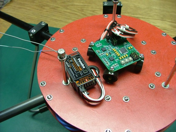
Before attaching the RX to the flight control board I drilled out a second 3/4 grommet hole in the upper hub disk to allow me to run servo extension leads to the bottom of the payload deck for future camera control channels. The receiver was then attached to the hub disk with some Velcro tape which has holes cut out to make clearance for the boom clamp screws below the RX (not shown).......
|
|
|
 |
|
|
I attached three servo extensions to the receiver: one to channel #6, one to channel #7 and one to the battery channel (not shown) for additional 5 volt power under the copter. Note: The receiver will be getting its power from the ESCs built in BEC or Battery Eliminator Circuits which are rated for 2 amps each! In essence there will be 12 amps of 5 volt power available to be used for lights and camera stabilization (granted the power buss in the RX unit can handle that much combined power!!!).
I highly doubt I will be using more than a couple of amps for such needs...
|
|
|
 |
|
|
And now I can finally attach the leads from the receiver to the flight control board. I made the same loop in the servo leads to isolate the control board as seen below......
|
|
|
 |
|
|
I am now only a few steps away from programming the speed controls and testing the flight control board for the first time!! Please join me again on the next episode of the MR1 Hexacopter Project.
Till then take care my friends!!
Don R. Giandomenico
|
|
|
|
|
|
|
|
|