GR-5 Turboshaft Engine Project 9/20/04

Posted on September 20, 2004:

       Well I finally had some time to get back into the GR-5 project so I dusted off my tools in the “bat cave” and went to work. I needed to test the horsepower output of the GR-5 so I could match the engine to a proper application. If the engine were to have less than 3 HP, I would probably use it as a demonstration unit or as the worlds first jet-powered margarita blender :0) If the engine were to produce 5 HP and up, I could use it to drive a vehicle.

       My hopes were high for a good HP rating as the engine had no trouble in swinging the 34” propeller. It would not be likely that the engine would be less than 3 HP but I had to make sure. During the last couple months I had received some e-mails with suggestions on how to make a dynamometer to test the horsepower of the GR-5. Most of them were fairly elaborate utilizing electrostatic braking and expensive load cells. I guess I asked it upon myself as I seem to “overcook” my projects with endless features.
       What I ultimately wanted was the HP rating and not a garage full of test equipment so I chose to go the cheap route and make a Prony Brake style dynamometer. The Prony Brake traditionally uses a rotating drum with a belt saddled over it. By using spring scales and a tachometer you can calculate the horsepower of the motor turning the drum. The method I wanted to use was similar but only uses one scale and employs a clamp style brake to go around the brake drum.                                                                                                                   

       I had an old spider drive coupling that I could use for my brake drum. Being made of iron, the drive coupling would be a great choice for a friction brake. I cut the drive teeth off the one side and mounted the drum onto the lathe. I bored a 3/4” hole into it for the drive shaft and broached a 3/16” keyway in the hole. After cleaning up the surface with a fresh cut, the drum was ready for use.

       I had purchased some Browning 3/4” pillow block bearings on eBay earlier and decided to use them to support a shaft that would be independent of the engine’s gearbox. I had also bought a 3/4” steel keyed shaft to drive the brake drum. I installed a spider coupling to the gearbox and to the 3/4” shaft to make the connection. Once the shaft assembly was complete, I laid out the framework to support the bearings and built a steel support that bolted onto the engine frame.

       I now needed to build my brake clamp that would fit around the brake drum. I had some non-asbestos remanufactured brake liners that belonged to a car that I did not own anymore so I cut them up to make the liners for my clamp system. I could of used a number of things for this but these were free. After I modified the brake liners I used a 4” pipe strap hanger to hold them. To actuate the clamp I used a pneumatic cylinder that can be controlled remotely.

       By using 1/4” steel rod, I welded on a brake arm that will attach to a spring scale. The arm is 12” from the axis of the brake drum to the pivot point at the end which will make the HP calculation easier.

       To keep cost down I chose to use a “fish scale” to measure the torque of the engine. The spring scale should be accurate enough to give me a plus or minus 5% reading. I made an arm to support the spring scale and installed two guide bearings on either side of the brake drum to keep the brake clamp in position.

       To make the test possible I needed a way to measure the RPM of the shaft and keep it steady. To do this I used a Omron photo optic sensor (not shown) in conjunction with a automotive tachometer to monitor the RPM. I anticipated a heat problem with the brake so I used a water mist spray head to spray water at the brake drum while running. To actuate the brake I used a air pressure regulator to deliver up to 120 PSI to the pneumatic cylinder.

       With all of the systems ready I fired up the GR-5 and tested the tachometer. Everything was looking good so I tested the brake by applying air pressure to the cylinder. After a few minutes of braking, the brake clamp was able to stop the drum from turning but created a lot of heat. I turned up the water mister to solve that problem and resumed testing.

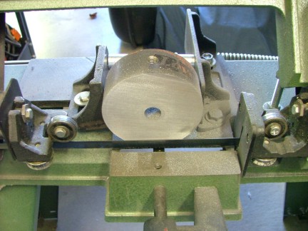
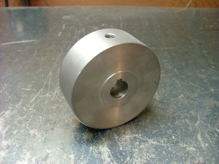
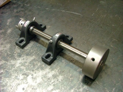
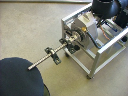
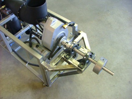
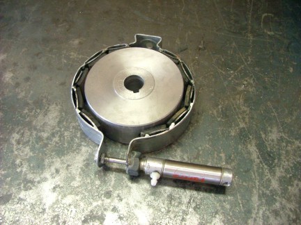
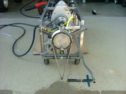
       With the engine running very well I brought the power turbine up to about 14,000 RPM. This put the drive shaft and brake drum at 2,800 RPM. I applied pressure to the brake while adding power to compensate for the drag. After three or four tries I balanced the RPM with the drag of the brake. Without going over 15 PSI combustor pressure or 925 deg. Fahr. EGT, I was able to produce 11.5 foot-pounds of torque @ 2,800 RPM.

                                     By using the horsepower formula:

                                 Horsepower = Torque (in lb-ft) x RPM                                                                                                                   5,252

                                       11.5 lb-ft x 2,800 RPM = 32,200

                                             32,200 / 5,252 = 6.13 HP

       I finally have the number I was looking for and not too shabby for a scrap pipe power turbine. I feel that 6.13 horse is enough to drive a ground based vehicle fairly well but not at the speed of sound. I was not surprised or disappointed at this measurement but it at least it is done and I can publish the horsepower rating at 6.13 HP @ 2,800 RPM*. I had messed around with different RPM/torque ratios and found that the higher RPM produced the most torque so without flogging the engine, this is a good conservative rating. *Further testing at a later date revealed that the GR-5A can produce 8 SHP @ 3600 RPM. See the GR-5A Demo Video.
       I am sure with some adjustments that I could get a few more HP out of the GR-5 but it could take a toll on the engine over time. I am just happy the the engine is running very stable and should be a great power plant for a vehicle of some kind. The next step is designing a vehicle to put the engine on so I can cruise around the block.

Till the next time..............

Don Giandomenico, Part-time gas turbine engineer :0)

[Home] [What's New At RCDON] [Articles] [Aircraft Projects] [Aircraft Videos] [Aircraft Videos II] [Experimental Projects] [GR-1 Turbojet Engine Project] [GR-5 Turboshaft Engine Project] [GR-5A Turboshaft Engine] [GRV-1 Turbotug Project] [GR-7 Turbojet Engine Project] [GRV-2 Jet Bike Project] [GR-6 Turboshaft Engine Project] [GR Engine Series Q&A] [Readers Projects] [Experimental Projects II] [My Collection] [RC Links] [About Myself] [Contact RCDON]