Vertical Boiler Project  4/10/11

Warning!!! The following articles are NOT plans for building a model boiler. There are no drawings or engineered specifications posted on these pages for a reason. These articles only serve as a record of my experience in building a vertical boiler. Please DO NOT try to use these articles as a guide to build you own boiler. They simply aren’t written for that purpose. Thank you...

Posted on April 10, 2011

       Hello again everyone. This week I decided to work on preparing the boiler shell for riveting to the end plates. This is an important step to engineer properly as there will be a lot of pressure on these end plates when the boiler is at full operating pressure. But before I can continue I must clean up the shell’s interior surface from the existing lime scale that was built up when this pipe was used as a water main for 20+ years of service!!!
       I used a 120 grit “flap wheel” to scour out the scale from the shell (seen below). The dust from the copper and scale was quite irritating to my sinuses so I learned to use a dust mask very quickly :0/

       This would be a good time to clean up the outside of the shell as well as it will be harder to do when the bushings and rivets are in place. Once again, dust mask required !!!

       WARNING!!! THE CALCULATIONS AND VALUES POSTED IN THIS ARTICLE ARE NOT TO BE USED AS A GUIDE IN BUILDING A STEAM BOILER!!! The specifications in this article are only to be used as a reference to this article and do not translate to any other boiler project. I must insist that anyone that wishes to build a boiler do their own research and use a properly written textbook like the Harris Book to design a safe boiler.
      
And now for the meat and potatoes of the process!!! To properly engineer the size and spacing of the rivets I must first know what forces will be applied to the end plates. This force value must then be used in a formula to calculate the size rivets needed to withstand 8 times that force. This will ensure that I will be operating the boiler within a reasonable safety margin allowing for any abnormal operating conditions.
       Earlier I had mentioned that I plan to build this boiler for 80 PSI working pressure. However it would be advantageous to build the boiler to operate at 100 PSI to allow for pressure spikes during operation of the steam plant. This will prevent my safety valves from blowing off every time I break 80 PSI while my engine is running!!!
       Since I know that my end plates are 5.845” in OD (2.923” Radius) I can calculate the square inch area of the plates as follows ( pi X R²):

                                           3.14 X 2.923² = 26.819 sq in

       I can now multiply my working pressure of 100 PSI with the surface area of an end plate:

           100 X 26.819 = 2681.9 pounds of force @ normal working pressure

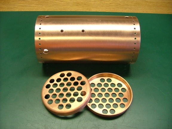
       In this application I will have a reduced end force on the plates as they are occupied mostly with the boiler tubes. In fact the boiler tubes will reduce the surface area of the end plates by 35%. Since the boiler tubes will double as boiler “stays” they will take up a majority of the end force applied to the end plates which will ultimately reduce the need for rivets. However I want to calculate my end force as if the boiler tubes have no tensile strength to be cautious.
       My boiler tubes (0.625” OD) will have a cross sectional area of about 0.307 sq in per tube for a total of 9.517 sq in (31 tubes). This value can be subtracted from the end plate area (26.819 sq in) which will equal about 17.302 sq in total end plate area. So now I can recalculate my end force as:

         100 X 17.302 = 1,730.2 pounds of force @ normal working pressure

       This will be the value that I will calculate as my end plate force and thus I will need to figure on a combined shear force of 1,730.2 pounds on the end plate rivets. According to the Harris book, copper has a shear rating of about 21,000 PSI which will be derated to a safety factor of 8. So I can divide 21,000 by 8 which in is equal to 2,625 PSI shear strength. Knowing this I can figure out how much rivet material will be needed to secure the end plates:

         1,730.2 ÷ 2,625 = 0.659 sq in cross section area of combined rivets

       I plan to use 3/16” copper rivets (0.1875” Dia.) to join the boiler shell to the end plates which will have a cross sectional area of about 0.0276” per rivet. Knowing this I can divide the total cross section value of the rivets by each rivet which will give me the total number of rivets needed:

                     0.659 ÷ 0.0276 = 23.89 (24) rivets total per end plate

       For this boiler I am going to increase my safety factor to about 10 for an extra safety margin as this is my first boiler (0.824 ÷ 0.0276 = 29.86). So instead of 24 rivets I will use 32 rivets which will be equally spaced on each end of the boiler shell (32 in lieu of 30 as it will space out more evenly). I will feel much more conformable with overkill rather than worrying about some factor that I did not take into account.
         To space out the rivets I will need to find the circumference of the boiler shell and then divide it by the number of rivets. In this case my shell is 6.125” OD which is equal to 19.2325” in circumference (pi X D).

                               19.2325 ÷ 32 = 0.601” rivet pitch spacing

       To lay out the rivet holes in the boiler shell I used my piece of vinyl sheeting which was marked out with graduated marks in 0.601” increments. It took several tries to evenly space out the holes but once the layout was even I was able to scribe the shell for drilling centers (seen below).

       At this point I laid out the boiler bushing holes and then center punched them for pilot drilling.

       The boiler shell was moved over to the mill for drilling of the pilot holes. I used the mill to get a better lock on the center punch marks I had made earlier.

       And now I drilled out the bushing holes as well as all of the rivet holes (seen below).

       Once all of the rivet holes were deburred I was able to re-polish the shell for assembly to the end plates.

       At this point I positioned the end plates so the boiler tube holes aligned with each other as seen below. I then drilled four 3/16” alignment holes in each end plate and temporarily mounted the plates with 4 rivets per side. The other holes in the end plates will be drilled in phases as the plates will more than likely shift during the riveting process making any previously drilled holes misaligned....

       The next step is to make some riveting punches to form the 3/16” copper rivets into place. These punches or “snaps” as they are sometimes called will be made out of 13/32” “water hard” drill rod or tool steel. This is a very hard but annealed tool steel that can be machined into shape and then hardened using a heat treating method.
       I cut up several 4” pieces to be made into my main rivet forming tools as seen below...

       The first tool I machined is the #1 forming punch. This punch has a 3/16” hole drilled in the end at about 0.225” deep. This tool will be used to “set” the rivet into place by bulging the neck of the “buck-end” of the rivet. Note: The buck-end is opposite end of the factory domed side of the rivet.

       The next tool I machined was the #2 forming punch which takes the previously “set” rivet and forms the buck-end to more of a cone shape. You will notice that the sides of the concave shape are cone shaped and not spherical like a typical rivet head would be (below)....

       The next tool was the #3 finish forming tool that puts the classic dome shape on the rivet. This tool had to be ground into shape with a Dremel tool to get the perfect cone shape. You can see below the rough machined dome before grinding......

       I used a custom shaped die grinder stone to cut a perfect dome shape into the tool steel. I kept the tool in an off-axis angle (with the lathe running in the opposite direction) which ground the hole in sort of a random orbital pattern making a perfectly concave impression.

       The last two tools I machined were the drawing-up punch and the dolly punch insert. The drawing-up punch is pretty much like the #1 forming punch except it has a 3/16” hole that is much deeper than the #1 tool (below, left in photo). This is so the tool can apply force to the plates and draw them together without hitting the rivet in the hole (more on that later). The face of the drawing-up tool is slightly domed to apply the most force where the rivet head will contact the plates being fastened.
         The dolly punch insert (Below, right in photo) is just like the #3 forming punch except that it is much shorter. This insert will be installed into a “dolly bar” which will be supported by my bench vise. The insert will transmit all of the rivet forming blows (from the other punches) into the dolly bar which in turn will absorbed by my bench vise and so on.
       Note: You may have noticed the grooves in the side of the tool steel. I cut these grooves to easily identify the order in which the punches are to be used starting with the drawing-up tool and ending with the #3 forming tool...

       The next step is to harden the punches by heat treating them. This is done by heating up the metal that you want to be hardened to a cherry red state. Once the metal is up to temperature you quickly “quench” the piece into a cold bath of water (hence the “water hard” tool steel description). However it is important to swirl the steel in the water to evenly cool the piece and prevent an uneven hardness.

       I heated up all five pieces of tool steel and quenched them into a bowl of water (seen below). This will harden the machined end of the punches which need to keep their shape during the forming process.

       At this point the tool steel is super hard but at the expense of being very brittle. In fact these tools would just shatter if I were to hit them with a hammer. To fix this I must temper the steel by reheating it carefully which will “relax” the steel and make it very tough. This is done by cleaning the previously quenched steel to a bright steel finish (not shown) and then carefully reheating the hardened area with a torch till it starts to change color.
       There are several states of hardness that correlate with the color “draw” of the temper. The lighter shades (tan/straw) being the most hard and the darker shades (blue/purple) being the most soft. I chose to draw a softer temper as I am working with copper, a soft metal. I heated up the punches with my torch till they were light purple (seen below). This should remove the brittleness from the punches making them safe to use.

       The next step was to make the dolly bar which will support the dolly punch insert. This bar will absorb the forming blows that will be transmitted through the rivet and into the dolly punch insert. I used 3/4” X 1-1/2” bar steel for this tool as it is heavy and robust....

       The dolly bar was drilled out to accept the 13/32” tool steel insert I made earlier. The beveled underside is to improve clearance from the boiler end plates....

       I installed the dolly punch into the bar as seen below. Just a few taps with the hammer and the insert was locked in place....

       I also welded on some bar stops that will keep the dolly bar from slipping in the jaws of the vise as seen below. Hopefully this setup will work without any further modification....

       I now have the basic tools for riveting up my end plates. I cannot wait to see if these new tools will work or not. Please join me again next week for the continuation of the vertical boiler project...

       Till then be the masters of your own craft my friends!!!

Don R. Giandomenico - fellow experimenter.....

[Home] [What's New At RCDON] [Articles] [Aircraft Projects] [Aircraft Videos] [Aircraft Videos II] [Experimental Projects] [Experimental Projects II] [Nixie Tube Clock Project] [6CI Steam Engine Project] [Vertical Boiler Project] [The Toolroom Tune-Up Project] [The Reverse Tumbler Project] [Red Wing Engine Project] [MakerGear M2 Project] [The LED Studio Light Project] [My Collection] [RC Links] [About Myself] [Contact RCDON]