 |
|
|
|
|
|
|
|
|
 |
|
|
 |
|
 |
|
 |
|
|
|
Posted on August 23, 2012:
Hello again folks. This episode I am going to tackle the connecting rod. This bronze casting is much like the one I machined on my 6CI steam engine project so I will be following the same approach as I had before.
|
|
|
 |
|
|
The first thing I did was clean up the molding flash with a set of files...
|
|
|
 |
|
|
I followed up the files with a fine wire wheel on my bench grinder. I was careful not to round over any corners by accident.
|
|
|
 |
|
|
The next step is to mount the rod in my milling vise and find the center of the cap with the wiggler tool.
|
|
|
 |
|
|
You can see the 1-2-3 blocks under the vise used for rod clearance...
|
|
|
 |
|
|
I zeroed out the table so that I could lay out the cap bolt holes.
|
|
|
 |
|
|
I used a #2 center drill to spot a bolt hole at .375 from center. I just put a divot in the surface so that the following drill will not catch the hole and mess up my bit.
|
|
|
 |
|
|
I followed up the center drill with a #19 drill at .5625 deep. I then drilled a #29 hole at the bottom of the #19 hole straight through the casting (not shown).
|
|
|
 |
|
|
Before moving the table to the other side I used a 3/8 end mill to spot face the cap at .025 deep.
|
|
|
 |
|
|
And now the other side...
|
|
|
 |
|
|
I marked the big end of the con rod at .6 from the rod side of the big end bearing and used my bandsaw to cut the cap off.
|
|
|
 |
|
|
I used my belt sander to carefully finish the inside faces of the bearing yoke. I ground the rod side of the casting down to 5.094 from the center of the wrist pin bore to the flat of the yoke (or about .540 from the inside edge of the con rod yoke). The cap was then ground to about .460 thick.
|
|
|
 |
|
|
I now used a 8-32 tap to thread the bolt holes at this time...
|
|
|
 |
|
|
I installed the cap bolts (included in the hardware kit) and then used a marking punch to identify the caps orientation to the rod (hard to see in the photo).
|
|
|
 |
|
|
And now to bore out the big end bearing. I set up the rod on my milling table and used the wiggler tool to find the center of the cap where the two halves meet.
|
|
|
 |
|
|
I used a #4 center drill to spot the hole just deep enough to keep the bigger drill from walking.
|
|
|
 |
|
|
I followed the center drill with a 15/32 drill bit straight through the casting. Note: Drilling bronze or brass with a big bit can sometimes be tricky. This stuff will catch a drill bit and wreck the part you are machining so careful patience is a must. I used the micro feed of my mill to advance the bit through the rod to ensure the bit would not catch when the hole pokes through the bottom. I also made sure that the crank was super secure on the table.
|
|
|
 |
|
|
I followed the 15/32 hole with a 1/2 chucking reamer at slow speed which left a beautifully smooth bore in the rod.
|
|
|
 |
|
|
The next step was to bore the small end of the rod. I had to be careful not to warp the rod with the forward clamp as there is no easy way to secure this end. I applied light pressure just behind the wrist pin collar and pinned the rod to a 1-2-3 block as seen below. The thickness of the unmachined rod ends are identical for the most part (about .624 thick) so shimming was not necessary to make the rod parallel with the table.
I lined up the spindle to the center of the wrist pin which was also right over a hole in the 1-2-3 block.
|
|
|
 |
|
|
I drilled out the hole with a 9/32 drill....
|
|
|
 |
|
|
I now chased the wrist pin hole with a 5/16 chucking reamer at slow speed.
|
|
|
 |
|
|
The next step is to trim off the sides of the ends so I mounted the rod flat on the table and removed .062 off of the big end as seen below. This is exactly half of the total material (.124) needed to be removed to leave a thickness of .5.
|
|
|
 |
|
|
 |
|
|
I flipped the rod around (same side facing up) to trim off the small end of the rod the same way. This has left both ends as about .562 in thickness.
|
|
|
 |
|
|
I now flipped over the rod and machined the other side to a thickness of .500 from the surface of the table. I also cut the small end the same way (not shown). Note: I was very careful to not warp the rod when clamping it down. Warping or bowing the rod would have left an uneven surface on the sides of the rod. I verified with my calipers that this was not the case after machining...
|
|
|
 |
|
|
I split the cap off of the rod and deburred the edges with a file. Not too shabby ;0)
|
|
|
 |
|
|
I decided at this point to check the fit of the big end on the crank. The cap clamped down nicely but was a little too snug on the shaft. To fix this I used some 600 grit sandpaper on a mandrel to fine tune the fit (not shown). I then reinstalled the rod with a little oil and it moved freely without any side play or rock whatsoever. A perfect fit!!!
Note: The general assembly drawing shows two sets of nuts being used on the bearing cap. I decided to use only one set with Locktite as I feel it is more aesthetically pleasing ;0)
|
|
|
 |
|
|
The last step was to drill out the oiler holes. I started with the grease cup hole which was laid out and centered up with the spindle.
|
|
|
 |
|
|
I drilled a #21 drill to .250 deep...
|
|
|
 |
|
|
Followed by a 10-32 tap as seen below.
|
|
|
 |
|
|
I set up my vise as I had done before and mounted the rod vertically to drill out the 3/32 hole that connects the bearings surface to the oiler hole...
|
|
|
 |
|
|
I centered up the spindle on the small end bearing oil hole and drilled it with a #1 center drill (not quite all the way through).
|
|
|
 |
|
|
Finally I drilled all the way through with a 1/16 drill bit to complete the rod assembly.
|
|
|
 |
|
|
I decided to brighten up the casting by tumbling it in walnut shells for a couple of hours in my vibratory tumbler. I added some Nu Finish car polish to polish the metal quicker. I did not want a mirror polish but only to brighten up the casting.
|
|
|
 |
|
|
The finished product...
|
|
|
 |
|
|
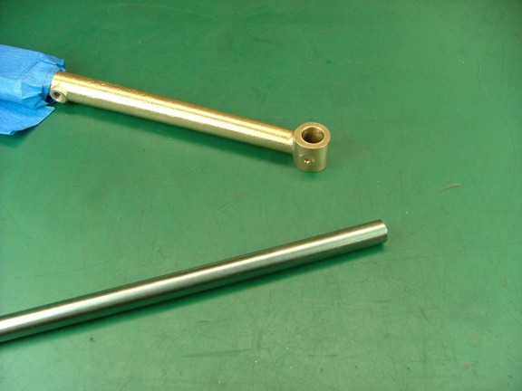
The next step is to make the wrist pin for the piston. The materials kit comes with some cold rolled steel for this part which will fit the bill nicely however I wanted something that would not wear too easily over time. I decided to use some 5/16 W1 tool steel to make the pin so it could be hardened.
|
|
|
 |
|
|
I decided to heat treat the rod before cutting it to length so I heat the rod up cherry red and quenched it in water.
|
|
|
 |
|
|
 |
|
|
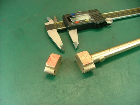
I now cut a 1.19 piece of the hardened end with my Dremel tool and a cutoff wheel. I then ground the ends on my belt/disc sander to a precision finish (not shown).
|
|
|
 |
|
|
The pin is now ready for tempering as it is too brittle at this point. I polished the metal so it was shiny and then slowly heated it up till it turned to a shade of brown yellow. The pin is now tempered and should last an extra long time.
|
|
|
 |
|
|
The pins diameter had enlarged .0005 due to the heat treating so I had to fine tune the bore of the pins collar with some 600 grit paper on a mandrel (not shown). I kept the pin snug so that there was no chance of any slop which will exacerbate wear later on.
|
|
|
 |
|
|
At this point I am ready to tackle the piston which I cannot wait to get into. I have never built a gasoline engine so a real piston made from bar stock seems like a challenge. Please join me again to see how I do in the next episode of the Red Wing Engine Project!!
Till then, keep building my friends!!!
Don R. Giandomenico
|
|
|
|
|
|
|
|
|