Hello folks! Paint and assembly are the only tasks left to complete before I run the Red Wing engine for the first time. Since the last episode I have disassembled the engine and cleaned all of the castings with acetone to remove any traces of oil.
One of the most tedious operations as well as my least favorite thing to do is paint :0/ Luckily this engine only has a few parts to paint which will ease my misery :0P I spent some time masking off the areas I didnt want to paint with blue painters tape and then carefully trimmed the edges with an Exacto knife (seen below).
The colors I am using for my engine will somewhat follow the original paint of the 5 hp Red Wing engine (example seen below). I will be painting my engine green and black however I will using a darker green than the green shown below. I will be substituting the original seafoam green with a leaf green which is the color I used on my 6CI steam engine project two years ago. Note: The photos below are courtesy of William Schaller of Red Wing Minnesota. The engine pictured below belongs to William and is one of two that are known to exist in the world!!! Not only that, this engine runs making it the only running 5 hp Red Wing in the world!!! William tells me that this is the very engine that was used to design the kit I am building!!! What an amazing piece of American history! Thanks William for sending me the photos and for preserving this beautiful machine!!!
For paint I will be using some Dupli-Color spray can acrylic enamel. This stuff has amazed me on how well it works on model engines. I had painted my 6CI steam engine over two years ago with this paint and have never had to touch up the engine which is saying a lot. I probably have over 50 hours of run time on the engine and the paint is still going strong even when covered in oil!!! Whats really amazing is this result was accomplished without using any primer under the acrylic!!! Just bare metal and paint!!! The acrylic does however have a kryptonite and that is blue Locktite :0P You must never get any threadlocker compound on the paint or else you will ruin the finish. Other than that the paint is fuel and oil resistant beyond any standard I have found in a rattle-can paint. The two colors I will be using on the Red Wing engine are semi-gloss black (Cat# DA1603) and leaf green (Cat# DA1630) which are seen below.
I really hate painting so I didnt take any pictures of that process however it did come out pretty good.
I used about three coats of paint which were sprayed within 15 minutes of each other. I coated the inside of the water hopper with a few coats of the black paint after the outer green paint was cured (not shown).
I allowed the paint to cure overnight before I handled the paint although I did remove all of the masking tape just minutes after painting. This was done quickly so that the paint edges could lay correctly before they cured.
The next step was to lay out all of the parts for final assembly which include over 275 individual parts and pieces!!!
Its kinda cool to see all of the parts laid out ;0)
So much time and effort although it is all going to pay off soon (I hope).
The first thing I worked on was to install the magneto into the engines base. I then bolted on the maple engine skids which really good in contrast with the dark green of the engine.
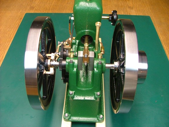
I now mounted the engine frame on the base and then I dropped the crank into the engine frame as seen below. I then adjusted the side play of the crankshaft so that it was even on both sides (about .012 on this engine). I then tapped the bushings up against the crank so that it will stay in the center of the bearing blocks when running.
I installed the bearing caps and then installed the hardware with a little blue Locktite (not shown). I was very careful not to get any of the Locktite on the paint as it will eat it like crazy.
The next thing to install is the piston. I lubed up the rings with some 10W-30 Mobil-1 motor oil and then positioned them so that the gaps were 180° apart from each other (seen below). I then compressed the rings with my fingers and slid the piston down the bore.
Next I positioned the big end bearing over the crank journal of which I also lubed with the Mobil-1 oil.
I now installed the bearing cap and tightened down the cap screws. You can see the blue Locktite compound on the cap stud below...
The next step was to install all of the timing gears. I used all of the alignment marks I had made earlier to set the gears correctly...
I now installed the poppet valves in the head making sure the right valve was in the right guide. I then set the top locknuts on the stems to .055 below the top of the stems on both valves. Once again, blue Locktite on the hardware...
And now for the head gasket and studs...
I installed the head now including the rocker arm bracket...
The compression release valve is the next part to be installed. I used some Permatex high temperature thread sealant (Cat# 59241) on the threads before installing it in the head. Note: I have used this type of thread sealant for years now and it is all I will use anymore. I have used it on my jet engine projects as well as my vertical boiler build with excellent results...
The release valve really adds to the scale look of the engine ;0)
The valvetrain linkage was next to go. Once the pushrod and rocker arm were secured I was able to reset the valve lash to .005 (not shown).
The next task is to assemble the fuel mixer. I used some of the thread sealant to seal the fuel orifice cap and needle valve fitting as seen below...
I had mentioned earlier in the build that I was going to substitute the 1.5 long mixer pipe with a shorter 1 nipple seen below. I decided to further modify the 1 nipple by cutting off the threads in the middle so it has a cleaner appearance...
I now installed the modified mixer pipe with some thread sealant as seen below. A much cleaner look in my opinion...
The fuel line was next to go. Once again more thread sealant...
And now for the muffler....
I now installed the drain plug in the scale location as seen below. No need for thread sealant here ;0)
The fuel filler neck was now installed into the engine frame. I applied some thread sealant at the bottom of the pipe and then tightened it into place using some soft-jaw pliers (not shown).
Next I installed the grease cups into the connecting rod and bearing caps. Thread sealant was used on these connections as well.
These miniature grease cups look great!!!
The next item to install is the drip oiler...
The drip oiler is another really scale looking accessory for this engine...
And now for the governor arm bracket...
The governor weights...
The latch out bar assembly is next...
Once the latch out bar was installed I adjusted the depth of the flywheel on the crankshaft so that the pawl of the bar was about .065 away from the top of the push rod plate (seen below). I also set the push rod plates end clearance from the pawl at .010 when the follower is at the top of the cam (not shown). This setting will ensure that the latch out system will correctly regulate the speed of the engine.
The flywheels were now fixed into place using the set screws which were treated with some blue Locktite...
Now that all of the parts are installed I could rivet on the nameplate...
Finally after many hours of work I get to see the finished product!!!
The engine really looks good with its new paint job :0)
I was unsure about the polished head but now I really like the mirrored look against the rocker arm and such. The black accents really set off the green as well...
The simplicity of the paint along with the natural beauty of the bare metals really make a attractive combination. What an awesome machine!!!
The next step is to prepare some fuel and see if the Red Wing engine will run or not. Please join me again when I fire up the engine for the first time on the next episode of the Red Wing project!!! Till then be well my friends!!!