 |
|
|
|
|
|
|
 |
|
|
 |
|
 |
|
|
|
Posted on June 19, 2011
Hey folks!! This episode I am planning to work on an autopilot system that will keep the hexacopter horizontal during FPV (First Person View) flying (and also night flying). An autopilot or flight stabilization system is a good idea when flying FPV platforms as you may sometimes need a little help leveling the aircraft when flying by the camera. This is especially true when you have lost video from the aircraft and are flying blind!!!
I do not nor will I ever suggest that you should rely completely on your video link to pilot a FPV platform. You should always have a spotter that has a set of eyes on the craft at all times for safety sake. I can remember flying my Video Cub via FPV and losing video signal. This of course was before any autopilot systems were popular to the FPV community. Lets just say I almost lost the plane, even with a spotter!!!
The truth is that a spotter can only tell you where the plane is so you can switch from viewing the FPV monitor to the actual plane. During this time a fixed wing aircraft can change attitude and crash within seconds without an on-board stabilization system. This is especially true for a helicopter system where there is little chance of saving the craft should the video link be interrupted.
My Sail-Cam AVP (Aerial Video Platform) uses a simple autopilot system that doesnt need a GPS signal or complicated software to learn to stabilize the aircraft in flight. That system is the FMA Co-Pilot FS8 (no longer made) and it has proven to be a really reliable system for self-leveling the aircrafts attitude automatically. I have since upgraded the Sail-Cam with an FMA Co-Pilot CPD4 2-channel system that can be used with 2.4 GHz receivers (seen below)......
|
|
|
 |
|
|
The FMA Co-Pilot CPD4 is a cost effective (about $60) flight stabilization system that works with the earths infrared energy to sense where the horizon line is. This information is picked up by a two axis IR sensor and then mixed into the pitch and roll controls to self right the aircraft day or night!!!
|
|
|
 |
|
|
The only drawback is that the CPD4 does not play well with some receivers and may require an additional advanced servo buffer to work properly. Since I am using a Futaba R6008HS 2.4 GHz FASST receiver I will need one of these servo buffers (FMA Cat# 606SB seen below) to delay the aileron channel slightly to allow the CPD4 flight computer to process the parallel Pulse Width Modulation (PWM) signals produced by the receiver.
I believe that the PWM signals on some receivers have the same peak-to-peak timing which can overload the input of the CPD4 and not allow proper time to process the information. The advanced servo buffer pushes the PWM signal of one of the channels off by 90° to fix the problem or at least that is how I understand it :oP Maybe future models of the Co-Pilot system will fix this issue.....
|
|
|
 |
|
|
When setting up the CPD4 you should test the system by installing it and using servos to test the output of the CPD4 unit to make sure that the PWM signals are smooth and not jittery throughout the whole transitions of both the pitch and roll channels. I had some initial problems with my Futaba 2.4 GHz receiver working with the CPD4 but I learned to adjust the off end point of the control auxiliary channel for the CPD4 in my computer radio to 135% which cleared up any jittery movement of the CPD4 outputs (along with using the servo buffer on channel #1 - aileron).
It seems like a hassle but in reality the system works really well once set up correctly and FMA has the only IR sensing system that I know of..
|
|
|
 |
|
|
I installed my CPD4 just next to the flight control board which easily tied into the servo leads from the receiver.....
|
|
|
 |
|
|
The CPD4 is super light and can be controlled remotely via a spare RX channel which is how I have mine set up. You will notice the advanced servo buffer on top of the wire bundle below......
|
|
|
 |
|
|
The next step is to install the IR sensor on top of the windscreen shield. This sensor detects the earths heat signature to compose an electronic horizon line that can be used by the CPD4 to level off the aircraft should it need assistance. I cut a small slot for the ribbon cable to exit the electronics deck shield as seen below......
|
|
|
 |
|
|
I installed the ribbon cable in the sensor and used double-sided servo tape to attach it to the shield (not shown). I then layered the cable on the underside of the shield as to take up some of the spare cable supplied with the sensor. I may decide to shorten it up later.....
|
|
|
 |
|
|
I secured the ribbon cable with some orange cellophane tape......
|
|
|
 |
|
|
The sensor cable was plugged into the CPD4 module and the programming was checked to make sure the system was controlling in the proper directions (pitch and roll). This was done by removing the propellers for safety and checking to see if the IR sensor was controlling the correct axis of motors when the heat of my hand was detected by the sensor....
|
|
|
 |
|
|
I took the hexacopter to my local park to test out the CPD4 system where I had some room to maneuver. The CPD4 was calibrated and I took off in manual mode to trim out the copter. I hovered at about 10 feet and then turned up the gain control channel for the stabilization mode making sure I still had control of the hex. The CPD4 started to take over keeping the copter level whenever I let go of the sticks :0)
I flew the copter around the park for a while getting used to the feel of the autopilot. Once I was confident with the system I tried a high flight with the hex where I flew up to about a 1000 feet!!! Note: I would not recommend doing this without a stabilization system as it is hard to tell what the hex is doing at that height. If the hex were to get off level it could tumble out of control and you would not be able to see it well enough to recover.
The copter was slowly lowered from its lofty position and brought back down safely with the aid of the CPD4. I was thoroughly impressed with the overall setup and decided to take the hex home for a final modification that would allow me to fly the hex at night!!! This of course would be to add navigation lights to the copter!!!
Actually one of my main reasons for building a hexacopter was so that I could fly at night. When I had seen Clay Sherrows hex fly at Tucson I was mesmerized by the LED lighting system he had and that is what sold me on the idea of building my own system. For my MR1 I am going to use a hybrid of navigation lights and UFO lights that can be controlled by the transmitter in flight....
The LED (Light Emitting Diode) controller system that I am going to use is a Dimension Engineering DELight LED lighting system. The DELight starter kit below has a programmable controller that runs of the receivers power to control up to six led control channels, 4-analog (0-100%) and two-digital (off-on). The $60 system comes with two 150 mA white LEDs, one green and one red 150 mA LEDs. I ordered an additional set of white LEDs for this project (seen below right).
I procured the kit from R/C Dude hobbies which really has me really impressed with their service!!!
|
|
|
 |
|
|
The DELight kit has a USB interface chip that connects to your computers USB port for programming the system which is really cool!!!
|
|
|
 |
|
|
The lighting controller (seen below) uses a similar programmable microcontroller chip as used in the hexacopters flight control board. It can retain over 100 blocks of programming information which is plenty of memory for all kinds of effects like strobe lights and beacons......
|
|
|
 |
|
|
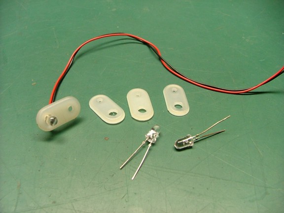
I will be using the factory 150 mA LEDs supplied with the kit as well as a set of traditional 5 mm LEDs which will be attached to ballast resistors to reduce the 5 volt control output to the required LED voltage. You will notice that the factory LEDs already have ballast resistors installed on led circuit boards (below)..........
|
|
|
 |
|
|
The DELight LED controller is capable of powering up to 4 amps of lighting power which is so cool!!! This will allow me to use my own LED lamps to create a UFO effect......
|
|
|
 |
|
|
I decided to start off my lighting install by rounding up some LED support tabs that I will make out of old landing gear straps from my collection of model airplane parts. These straps are similar to Goldberg 1/2 landing gear straps (Cat# 291 - Tower Hobbies Cat# LXDMG5) although the ones seen below are a little thicker. Both types work well for holding 5 mm LEDs once drilled out......
|
|
|
 |
|
|
I drilled out a set of the nylon straps to hold the LEDs tightly in place......
|
|
|
 |
|
|
Because I am using some of my own LEDs with the DELight system I will need to install a set of ballast resistors to correct the LED current supplied by the 5 volt BEC (Battery Eliminator Circuit) on the ESCs (receiver power). You can see the resistors that are soldered in series with the power wires below. I will also be using a common power wire system that will eliminate the need to run two wires to each lamp.
Note: The DELight lighting controller uses NPN transistors as its output to control the LED channels so that means that the switched leg of the circuit is the NEGATIVE output pin from the board. That means that the common wire must be the positive output pin or wire from the LED connector or else the controller will not work properly!!! For example: Three LEDs can be connected to a single positive common wire whereas the negative side of the LEDs must have one wire each running back to the controller (four wires - three negative switch legs and one positive common for a three LED system)......
|
|
|
 |
|
|
I used the landing gear straps to mount the LEDs to the motor mounts as seen below. The LED power wires were then routed inside the motor booms into the main hub.....
|
|
|
 |
|
|
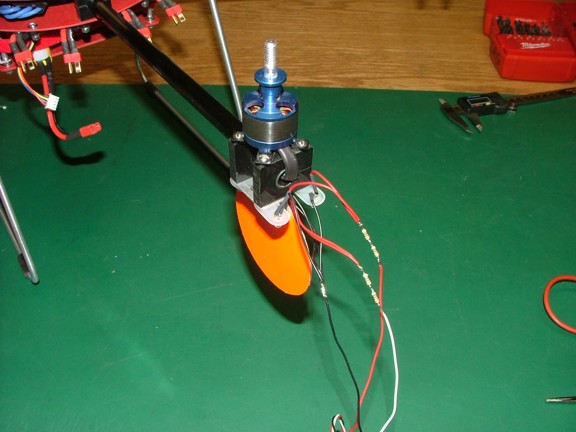
You can see below four LEDs that will be used to illuminate my tail fin paddle. Being able to see the paddle at night will be crucial to navigating the hex........
|
|
|
 |
|
|
And now to test the first set of LEDs!!!!
|
|
|
 |
|
|
The next step was to mass produce the rest of the LEDs and tie them into the common wire system I am using......
|
|
|
 |
|
|
And now to test them out before installing them......
|
|
|
 |
|
|
I also installed several of the DELight system LEDs on the copter for the navigation lights. Two of which were used as headlights as seen below....
|
|
|
 |
|
|
I used double-sided servo tape to hold the 150 mA LEDs to the copter as seen below......
|
|
|
 |
|
|
I soldered up all of the wires inside of the hub of the copter (not shown) and then ran all of the servo style plugs up to the controller. I then plugged the controller into a spare channel on my receiver so it can be controlled by the transmitter in flight......
|
|
|
 |
|
|
One of the last steps was to program the DELight controller using the free downloaded software for the system (screen shot below). I was able to incorporate several lighting scenarios including phasing lights and strobes that are really unique to this system. Because the system is PC based you can save custom programs and load them easily to change the settings whenever you want. In fact I can e-mail my program to anyone should they want to use it for their project :0)
|
|
|
 |
|
|
And now the moment of truth!!! I plugged in my batteries and tested out the system in the garage. I switched on the first setting for the navigation lights and was pleased to see the super bright 150 mA LEDs light up the garage!!!
|
|
|
 |
|
|
The nav light scenario uses red and green sidelights as well as a set of bright headlights that give the copter a deep-sea ROV kind of look :0) The copter also has a set of white strobe lights in the booms directly behind the sidelights (not shown). The last set of lights is a pair of white 5 mm LED tail fin paddle illuminators (seen above) which shine downward to help the pilot see which way the copter is pointing at night.....
|
|
|
 |
|
|
Now the next lighting scenario is the UFO lights which is strictly for fun and not for fooling the neighbors into calling in a UFO to the Air Force :0P These lights are comprised of a set of bright blue LEDs on all six booms as well as a red and green phasing light on the bottom of the battery tray......
|
|
|
 |
|
|
The red and green lights have been programmed to phase from one to another which is a really cool effect. You can see above where the two colors mix to make a yellow glow under the copter......
|
|
|
 |
|
|
While the center hub LEDs phase from red to green to red, the outer blue LEDs pulse in and out of phase of each other. This is a really cool effect and can be easily modified using the DELight programming interface.......
|
|
|
 |
|
|
See the MR1 Hexacopter Demo Video Here !!!
|
|
|
 |
|
|
I just had to try out the system at night so I drove over to the local park and flew around for a few minutes. The copter was so easy to see in the sky with both lighting scenarios. I had no problem at seeing what the copter was doing at any attitude. The FMA Co-Pilot system was also helping me out making it a very relaxing experience. The only stress I encountered was the growing crowd of people wanting to know what it was :0P
I had all of the local dogs barking from their yards as they noticed the strange lights in the sky. The ESCs also make a cool high pitched whine that surely would sell UFO to even the toughest of skeptic ;0)
|
|
|
 |
|
|
Update, July 10, 2011:
I have recently added a new UFO triangle light to the hex that is really bright!!! The triangle is made of square carbon fiber tube and is 44 long at each leg. I installed a set of LED lighting strips that have 306 surface mount LEDs producing a total of 20 watts of light. The bottom 99 LEDs are RGB color changing units that are powered by a light controller with an infrared remote control. The new light system can be seen over five miles away!!!
See the UFO Triangle Light Demo here!!!
|
|
|
 |
|
|
Wow, I really enjoyed building this project and I cant wait to use the copter to do some aerial video or FPV flying (or maybe just tease the local dogs :0) I hope that my documentation is useful to some builders out there and I welcome any questions or comments about the project should you have any. Thanks for reading!!!
Don R. Giandomenico
|
|
|
|
|
|
|