 |
|
|
|
|
|
|
|
|
 |
|
|
 |
|
 |
|
 |
|
|
|
Posted on June 14, 2011
Hey everyone!! I am almost ready to test out my new hexacopter and I am sooooooo excited!!! I just have a few details to sort out and then I can test the new flight control board. One of the last things I need to do is make a protective shield for the electronics deck of the copter. This shield or windscreen will provide protection from any accidental water spray or foreign debris that the propellers may bat into the electronics deck.
The propellers are near the same level as the flight control board and if one were to shatter on an object it could take out my sensitive control board. This is why I am going to make a clear plastic shield to protect the electronics and still allow me to see the LED indicators on both the control board and my receiver...
|
|
|
 |
|
|
To make my new windscreen shield I am going to use the old cardboard template method. I used a piece of manila folder paper to make a template of the top and upper hub disks so that a clear plastic sheet can be cut out to mount to the top disk. I rubbed the paper with my fingers to make the impression of the disks so that they could be duplicated on the clear plastic sheeting......
|
|
|
 |
|
|
I will be using some K&S Engineering .030 thick clear plastic sheeting (K&S Cat# 1306 - Tower Hobbies Cat# LXR783). This stuff is pretty durable and can be cut using small scissors.
|
|
|
 |
|
|
I added some mounting tabs to the paper template so the windscreen can be mounted to the top FRP disk with 2-56 screws. I then traced out the template on the clear plastic as seen below. you will notice the overlap mark at the ends of the template. These overlapping ends will attach to the second half of the windscreen.....
|
|
|
 |
|
|
I cut out the windscreens using some Hobbico canopy scissors as seen below.......
|
|
|
 |
|
|
After both windscreen shields were cut out and the tabs were bent into position I was able to use some blue painters tape to hold them in place for drilling.....
|
|
|
 |
|
|
Using a 3/32 drill bit I was able to make all of the mounting and joining holes in the new windscreen......
|
|
|
 |
|
|
I cleaned up the plastic sheeting with some Mequiars clear plastic polish to remove any fine scratches before assembly (not shown)......
|
|
|
 |
|
|
I used a set of 2-56 18-8 stainless steel screws and nuts to join the two Halves of the windscreen together as seen below....
|
|
|
 |
|
|
Next was the windscreen to the top shield disk that I made earlier to protect the electronics deck......
|
|
|
 |
|
|
I bolted on the windscreen shield to the copter and it fit beautifully :o) I will now be able to see all of the cool electronics, sort of like a display case.....
|
|
|
 |
|
|
The next step was to build some antenna supports for the 2.4 GHz receivers dual diversity antennas. These antennas need to be pointed at 90° from each other for the best reception so I cut out a set of the Sullivan 2-56 Gold-N-Rod pushrod tubes to hold the antennas inside.
|
|
|
 |
|
|
I used two short pieces of 1/8 ID Tygon tubing over the base of the antenna tubes to better hold the tubes in place. I then used some clamp ties (McMaster-Carr Cat# 7295K12) to secure the antenna tubes to the boom clamp screws as seen below ..........
|
|
|
 |
|
|
The last thing to do was cut out two notches in the windscreen shield for the antennas.......
|
|
|
 |
|
|
The next step was to install the propellers on the MR1. I will be using a set of GWS HD9050x3 (9 dia x 5 pitch) 3-blade propellers that I tested with my motors earlier in the build (not shown). These plastic props come in normal rotation and counter-rotating styles which is a must for multi-copter use. The GWS 3-blade series props are the best (IMO) for mulit-copters as they are really flexible which helps keep them together during rough landings or slight contact with objects during flight.
However these props will break at the root should they come in contact with something solid which is a good thing considering it could be a body part!!! Make no mistake, these thin plastic blades can still be a danger to observers but much less dangerous than the fiberglass reinforced, sharp tipped Ginsu bladed props I have seen on most electrics these days :0P Considering there will be 18 blades whipping around this craft I will go with the flexible kind :0}
Note: These GWS 3-blade props pull pretty good for a flexible blade prop but maybe not as much as a rigid style 2-bladed APC electric prop.
|
|
|
 |
|
|
I purchased these props from a really cool hobby shop called R/C Dude Hobbies in Oregon which sells the GWS props individually. Randy Moody of R/C Dude is a fair person to deal with and they are serious about getting your order to you quickly, I appreciate That!!! You can also purchase these props in quantities of 6 and 100 units from Caliber Hobby which is the online storefront for GWS in California.
These props come in an unbalanced state so they do need to be tuned up before mounting on a motor. I use a Dubro Tru-Spin prop balancer (Dubro Cat# 499 - Tower Hobbies Cat# LXD712) to balance all of my props. I like to shave the leading edge of the blades (that are heavy) with a #11 Exacto blade held perpendicular to the propeller blade being shaved. I drag the blade against the prop to evenly shave the leading edge in a round nose shape until the propeller balances out.
I have had incredibly good results with this method on plastic and glass filled propellers alike.....
|
|
|
 |
|
|
Earlier in the build I had made a tail fin bracket for a paddle that will visually indicate to me which way the copter is flying. It was now time to make the paddle to install on that bracket so I cut out a 3 disk of 1/16 FRP sheeting for my tail fin paddle.....
|
|
|
 |
|
|
To make the paddle more visible during flight I used some day-glow trim sheeting which has an adhesive back to it. I just peeled and stuck the sheeting on the disk and then trimmed to the outside edge.....
|
|
|
 |
|
|
I drilled two holes in the paddle and mounted it to the bracket as seen below. There will be no missing this indicator!!! It sort of reminds me of a tail rotor on a conventional helicopter.......
|
|
|
 |
|
|
At this point I checked the programming of the ESCs to determine that the proper settings were correct for this application. I used an Exceed-RC ESC programmer to link to the individual ESCs (not shown) and checked the following parameters: Brake Function - Off, Battery Type - LiPo, Cut Off Type - Soft Cut, Cut Off Voltage - Low, Start Mode - Normal, Timing Mode - Low, Music Mode - Off ;op and Governor Mode - Off
I was now ready to setup the ESCs with the flight control board. I plugged in the batteries and followed Ken Duffeks flight control board instructions for setting up the throttle range of the ESCs. Note: This step is super critical to do right or else the ESCs will not arm when power is applied to the system. The ESCs were set and and I was able to test the proper direction for the aileron and elevator channels as described in the board instructions.
I also checked that the gyros were acting in the right direction by carefully holding the copter by the skids and powering up the motors to see if the motors would fight any change in attitude. Luckily all the gyros including the yaw (rudder) gyro were all working in the correct direction without changing the flight control boards settings. Note: it is a good idea to wear safety glasses when testing the flight control board at close range.
I would strongly recommend that you are extremely careful when testing any multi-rotor aircraft as that you dont inadvertently throttle up and hurt yourself!!! I would suggest that you do as much testing without propellers installed and then, when you do install the propellers be sure you clamp down the craft so it cannot take off accidentally and hurt anyone. These machines have a lot of power and sharp propellers on all six points!!!!!
|
|
|
 |
|
|
I weighed the copter for a final weight and read 1900 grams or 4 pounds-3 ounces without batteries. After adding the battery packs I read 2636 grams or 5 pounds-13 ounces total. Not a lightweight but capable of producing 9 pounds of thrust @ 1.5 HP (1120 watts) for over 4 minutes.
|
|
|
 |
|
|
 |
|
|
 |
|
|
I started my testing process in the front yard trying my hand at hovering. It had been a while since I played with my helicopters so there was a bit of a learning curve before I was comfortable with the hex. I removed the windscreen shield and spent some time dialing in the three gain adjustments on the gyroscopes. I set up the pitch and roll gains so that they were a 1/8th of a turn back from the copter starting to oscillate when hovering (about 75% clockwise). The Yaw gain was set up at 90% as it will not oscillate as the other functions will.
I had noticed that I had to add some trim to the yaw or rudder input to keep the copter from pirouetting. After some trial and error I learned that any trim off of center on the rudder stick would take away from the rudder authority on that side of the stick. By this I mean that added right trim on the rudder would ultimately take away from full-right rudder and sometimes the copter would not respond to that control command.
To fix this problem I learned to trim out the copters rudder stick by returning the trim to zero and tilting one or a few of the motor mounts in the opposite direction of yaw. This process was done by adjusting the motors and then trying to hover several times until the trim was close enough to fix with a few clicks of trim on the radio. Now the copter had rudder authority in both directions :0)
Note: Always check to see that the motors on the copter have not tilted or rotated on the booms during transit or while in storage as it could cause the copter to fly out of control upon take off. It is a good idea to slowly take off every flight and hover close to the ground until you are sure the rudder trim is neutral. It only takes a little tilt on one of the motor booms to spin the copter in a pirouette.
It is also worth mentioning that the closer you get to the maximum lift capacity of a hexacopter the more you risk reduced control due to yaw gyro correction. When the yaw gyro senses turning it will compensate by spinning up the three counter-rotating rotors to induce a counter-torque into the hexs frame. This function is accompanied by reduction of speed of the three alternate propellers which also helps induce the counter-torque into the frame.
Unfortunately this action puts a lot of stress on the three yaw countering motors as they are doing most of the lifting. As you approach the lifting capacity of the hex you may overcome the ability of motors thrust to correct a yaw change and the hex may start to fall during a rudder correction. This scenario can be aggravated by a low battery pack or overheating ESC so care must be taken when maneuvering with a heavy load!!!!
|
|
|
 |
|
|
Now that I was getting better at it I decided to show my buddy George Manning how the copter flies and we flew it several times at the local college ball field (not shown). After George flew it a bit he discovered that by adding +35 exponential to the rudder channel and -45 expo to the aileron and elevator that it flew much better. I gave it a go after he made the adjustments to the radio and I was amazed at how much better it flew. It really reminded me of a well adjusted RC helicopter!!!
Also, the tail fin paddle I installed earlier was working great at indicating position of the copter however I may need to make the paddle smaller as it weathervanes a bit too much in a cross wind......
|
|
|
 |
|
|
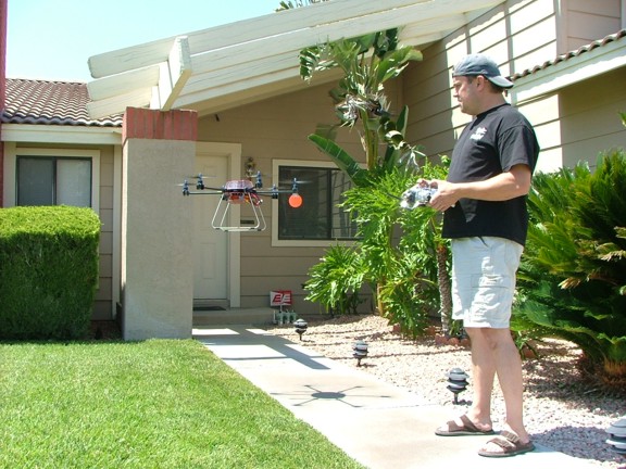
I spent some more time studying the copter and getting used to how it flies in my front yard while stopping every car that passed by :0} Everyone wanted to know what it was, it actually became very distracting :0P I was getting about 11 to 12 minutes of hover time and 9 to 10 minutes of moderate forward flight (without a payload). The Integy on-board battery checker unit was working very well at the 3.5 volt per cell cut off leaving me well over a minute of time before I was in danger of power stalling the craft.
After charging several sets of batteries it seems that I am yielding about 8200 mAh from the packs which is far from damaging them due to over-discharge. In fact the packs seem to be doing good as they are maybe 100 to 115° F after a full run!!! I also checked out the motor temps and read an average of 150° F (with a 10 ounce payload - 6.5 pounds total flying weight) which is fairly reasonable.
The 30 amp ESCs I am using handle the current very well but need ample ventilation as I found one of them overheating due to wires blocking its ventilation. When most types of ESCs overheat they protect themselves by reducing power output which in this case could cause a loss in control!!! It is a good idea to monitor your ESC temperatures with a non-contact temperature gun during the first few flights, especially during heavy lifting!!!!
If your speed controllers are getting too hot (over 150° F) you can install some home-brew heat sinks under the heat shrink tubing material on the ESCs. Just cut some .030 thick aluminum sheeting into 3/4 wide strips and slide them under the heat shrink tubing on top of the factory heat sink (on the side of the ESC with the MOSFET transistors). Leave a 1 to 2 tail of the sheeting so it sticks out into the open air and your heat problems are gone ;0)
|
|
|
 |
|
|
See the MR1 Hexacopter Demo Video Here !!!
|
|
|
 |
|
|
I decided to see how much weight the hex would comfortably lift so I cut a couple of 2 x 4 blocks that weighed 20 ounces each and laid them into the skids (not shown). I rolled up the collective and the copter was off!!! It was lifting 2.5 pounds easy and still had control :0)
|
|
|
 |
|
|
Another test I wanted to perform was to see what the current draw was at hover and at full thrust. I used two battery packs and two amp/watt meters on the battery pigtail connectors and then hovered the hex for a while in the yard. It seems that at hover the copter draws about 6 amps per motor or 36 amps total without a payload. The copter was then clamped down to my workbench to see what full thrust readings look like and I measured 17 amps per motor which is right around 100 amps total (I used 1/4 copper tubing pieces to shunt out the 30 amp fuses for this test).
These particular brushless motors seem to handle the short bursts of full power (17 amps) just fine with no smoke :oP Although I do believe that they are best if run below 13 amps continuous @ 150 watts or they may overheat....
|
|
|
 |
|
|
I have now flown the hex about 15 flights now and I am really enjoying it. In fact I am already thinking about my next hexacopter project :0) I cant seem to get over how stable the craft is and how unique it looks. I know my son Vincent (below) really enjoys watching it fly :0)
|
|
|
 |
|
|
Well you might ask what is next and for me and that would be to work on a autopilot system that will maintain horizontal flight. I will need an autopilot system when I start experimenting with FPV or First Person View piloting where I fly by the camera. I have some experience with an autopilot system through my work with the Sail-Cam Project. I hope to use the same autopilot on my hex to make it even more versatile.
Please join me again for the next episode of the MR1 Hexacopter Project!! Till then keep learning my friends!!!!
Don R. Giandomenico
|
|
|
|
|
|
|
|
|