 |
|
|
|
|
|
|
|
|
|
|
 |
|
|
|
 |
|
 |
|
 |
|
|
|
Posted on September 7, 2010
Hello folks! The moment of truth is at hand! Just a few paper gaskets are all thats keeping me from running the engine at this point. The gaskets seal the upper and lower heads of the cylinder block which would leak quite a bit if they were missing. I wanted to take my time and properly cut the gaskets so that they would be good enough to use on the final assembly once the engine is painted.
|
|
|
 |
|
|
The gasket material that was supplied with the kit seemed a bit too small for the diameters of the cylinder heads. I had to undersize the gaskets to fit both of the large cylinder head gaskets on the one sheet of gasket material (not by much though). I laid out the basic shape of the gaskets on the material with a compass as seen below...
|
|
|
 |
|
|
Using my scissors and an Exacto knife I cut out the shapes.
|
|
|
 |
|
|
I put the gaskets on the cylinder block and then laid the valve and cylinder heads over them so a pencil mark could be made through the screw hole centers.
|
|
|
 |
|
|
Using the pencil marks as layout I punched out all of the screw holes with a couple of hole punches as seen below.
|
|
|
 |
|
|
I could now start assembling the engine for testing!!!
|
|
|
 |
|
|
The gland seals on both the lower cylinder head and valve head needed to be installed. The kit uses a piece of Teflon rope material that is wound around the push rods and then held in place with a packing nut.
|
|
|
 |
|
|
I installed two full turns of the packing material and then installed the packing loosely for future adjustment.
|
|
|
 |
|
|
The piston rod was screwed into the crosshead and the piston was centered in the bore so the stroke was equal on both sides. The valve was also centered in the bore at this time. I set up the eccentric to the approximate timing angle of 82° behind TDC and locked it into place before proceeding (not shown).
|
|
|
 |
|
|
I bolted on the upper heads and then installed a 1/8 NPT nipple and elbow for the steam inlet. In this case I will be using compressed air to test the engine until a suitable boiler can be built.
|
|
|
 |
|
|
The engine is really looking good at this point :0)
|
|
|
 |
|
|
One last thing I needed to do was seal off the cylinder drain ports so I could test the engine. I have plans to install miniature globe valves on the drain ports but I am not ready for that yet. To plug the open holes I used a set of 3/16 x 40 close nipples that had been crimped off on the end, acting like a pipe plug.
|
|
|
 |
|
|
And now the moment of truth!!!! I installed an air hose coupler to the engine and then hooked up my shop air hose to the coupler. I checked that the engine was oiled up on all of the mating surfaces including a 1/2 ounce of cylinder oil in the steam inlet before proceeding. I started adding air pressure to the engine using a regulator looking for signs of life.
I gave the flywheel a little nudge and tic-tic-tic-tic-tic, she was running!!!
|
|
|
 |
|
|
I kept the engine at 80 RPM for a while as I watched for any trouble signs including scraping or galling. Luckily the engine kept increasing in speed as time went by (with the same air pressure applied). The friction caused by the mating parts was starting to ease up as the parts slowly broke in. I kept oiling the engine and stopping it to add cylinder oil to the steam inlet port.
|
|
|
 |
|
|
By now the engine is sounding like a sewing machine (quite literally). I ran it for about 10 minutes before I started playing with the speed. I ramped up the RPM to about 200 and observed the balance of the engine. I had noticed that there are sweet spots at certain RPM in where the engine hardly vibrates (harmonics). I explored that phenomenon for a while as I worked up to about 250 RPM (the suggested maximum RPM).
Unlike gasoline engines, the steam engine can produce torque at any speed so revving up the engine is pointless when power output is concerned. A moderate speed can produce a lot of work with a steam engine so I can see why they suggest such low speeds. Besides the engine vibrates quite a bit over 250 RPM :oP
|
|
|
 |
|
|
Both the valve train and connecting rod assemblies are working flawlessly now. I am amazed at how quiet the mechanics are considering that I machined then in my garage. The crosshead was making a quiet zipping/swishing sound as it slipped down the guide. This must be caused by the lathes tool bit marks rubbing against the bore of the frame. In fact I could see the guide being worn in by the crosshead as the engine continued to run.
|
|
|
Video coming soon!!!!
|
|
|
 |
|
|
By now I had run the engine at a number of different RPM and was quite happy with its performance. The next step was to install a needle valve next to the steam inlet port to be used as a throttle valve. I had purchased a high quality needle valve from McMaster-Carr (Cat #7833K75) for this purpose. The needle valve was installed as close to the steam inlet port as possible to promote precise flow control.
The new valve was tested with a head pressure of 100 PSI and worked like a charm. In fact the valve almost works like a governor granted the head pressure stays constant. I tried to stop the flywheel at a given speed and the engine only slowed down a little as it adjusted to the increase in cylinder pressure.
|
|
|
 |
|
|
I was truly amazed at the torque the engine could produce at a 100 PSI!!! I used a rag to press against the flywheel for friction and almost could have started a fire!!! This engine is quite powerful!!!
|
|
|
 |
|
|
Speaking of power, as the operator of this beast you have to be careful not to get any fingers caught up in the engine or YOU WILL LOSE THEM!!! This thing isnt stopping for much so extreme caution must be used when demonstrating this engine, especially with kids around!!!
|
|
|
 |
|
|
I disconnected the air line and gave my compressor a well needed rest :0) The oil was mopped up off the table and I started to disassemble the engine for painting. However I had one more step I had to complete before the parts could be prepped for paint and that was to install the cylinder lagging jacket.
The cylinder lagging is sort of an insulating jacket that helps to keep the cylinder up to the operating temperature of the incoming steam. If the cylinder gets cooler than the incoming steam it will begin to condense the steam in the cylinder and form puddles of water. This water can cause problems and reduce the efficiency of the engine.
This kit is supplied with a piece of brass sheeting to be used as the lagging jacket. Of course it needs to be formed around the cylinder as well as drilled for the mounting holes, steam inlet pipe and drain ports. The prints do not elaborate much on how this process is supposed to be done so I had to develop my own method.
|
|
|
 |
|
|
I started out by marking where the steam inlet port will protrude out of the lagging jacket. For this I measured 3.225 up from one end of the uncut sheet and made my mark.
|
|
|
 |
|
|
The next step was to punch a 7/8 hole into the brass sheet with a chassis punching tool (a hole saw will also work)....
|
|
|
 |
|
|
 |
|
|
The next step was to form the sheet to the cylinder block. I used a piece of PVC pipe to form the small radius bend near the valve chest (below).
|
|
|
 |
|
|
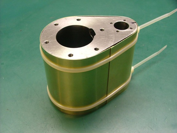
And now the sheet was strapped to the cylinder with nylon cable ties. Notice the overlap of the sheet at the bottom of the cylinder...
|
|
|
 |
|
|
The kit was supplied with twenty-two 2-56 filister head screws for attaching the lagging to the cylinder. This seemed to be an odd number but I was going to make it work anyway. I measured out the circumference of the cylinder with the brass sheeting installed and came up with 10.875. I divided this number with 11 (half of 22) and came up with a screw spacing of .9885.
Using a strip of blue painters tape I was able to make a story pole type of a measuring device. I marked out where all of the screw centers were on the tape and then applied the tape to the cylinder for layout.
|
|
|
 |
|
|
I marked on the side of the cylinder where the tape marks were (not shown) and then removed the tape for drilling.
|
|
|
 |
|
|
The next step was to drill out all of the screw holes in the cylinder at about .15 in from the edge of the brass sheet. I used a #50 drill (.0700) for this task and drilled them to about 5/16 deep.
|
|
|
 |
|
|
Unfortunately there were four 10-24 cylinder bolt holes that intersected with the 2-56 holes. I decided to keep the screws evenly spaced and just trim the 2-56 screws shorter to allow clearance for the cylinder head screws.
|
|
|
 |
|
|
Now that all of the holes were drilled and cleaned out I could tackle the most challenging tapping job to date!!!
|
|
|
 |
|
|
These 2-56 screws are truly tiny and it takes a tiny tap to thread these holes. Now if you have ever spent any time tapping metal you have probably encountered a broken tap. In this case it would be very disheartening to lose a screw hole to a broken tap :0( This is why I was particularly careful when tapping these holes.
First off I used an old drill chuck to act as a tap handle for the tiny tap. I used an ever-so-gentle technique of screwing in the tap and then feeling for the resistance of the tap as it gets mired in the cast. I then backed out each hole and cleaned them from cutting oil and shavings. The holes were then re-tapped a little deeper until the lagging screws had the proper clearance.
It seemed at any moment during the 1-1/2 hour process that the tap would break but it held out through all 22 holes!!
|
|
|
 |
|
|
I widened the #50 holes in the sheet brass to 3/32 holes on all 22 holes. I then added the two 5/16 drain port holes in the bottom of the lagging as seen below.
|
|
|
 |
|
|
I trimmed four of the lagging screws (.09 shorter) to fit into the shorter screw holes as mentioned earlier.
|
|
|
 |
|
|
You can see that the short lagging screws worked beautifully while still missing the cylinder head bolts....
|
|
|
 |
|
|
Well, all I have left to do now is paint the engine and mount it on some sort of display board. I will get cracking on the paint job as well as work on a demo video so you guys can see her run!!!
Until then, take care my friends and stay tuned for the continuation of the 6CI project!!!!
Don R. Giandomenico
|
|
|
|
|
|
|
|
|